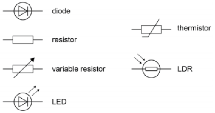
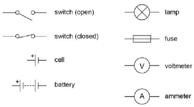
Component symbols
What is electric current?
Electric current is a flow of electrical charge (electrons). Electric current is the amount of charge that flows past a point in a circuit or through a component in a given time period – the rate of flow of charge.
The equation for charge flow is:
Charge flow = Current x time
Q = I x t
Q = Charge flow (C)
I = Current (A)
t = time (s)
Current is the same at any point in a series circuit.
In a parallel circuit, the current splits at the branches, so that the total current leaving any point = the total current entering that point.
For electrical charge to flow through a closed circuit the circuit must include a source of potential difference. A source of potential difference could be a cell/battery or mains power (from a socket).
Ohm’s Law
Ohm’s law links current, potential difference and resistance. The equation for Ohm’s law is:
Potential difference = Current x Resistance
V = I x R
V = Potential difference (V)
I = Current (A)
R = Resistance (Ω)
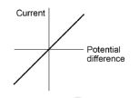
The current (I) through a component depends on both the resistance (R) of the component and the potential difference (V) across the component.The greater the resistance of the component the smaller the current for a given potential difference (PD) across the component.
The current through an ohmic conductor (at a constant temperature) is directly proportional to the potential difference across the resistor. This means that theresistance remains constant as thecurrent changes.
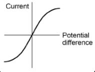
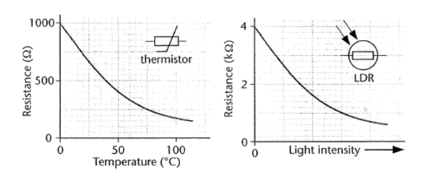
The resistance of components such as lamps, diodes, thermistors and LDRs is not constant; it changes with the current through the component.
The resistance of a filament lamp increases as the temperature of the filament increases
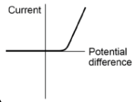
The current through a diode flows in one direction only. The diode has a very high resistance in thereverse direction.
The resistance of a thermistor decreases as the temperature increases.A thermistor could be used in a thermostat to detect changes in temperature.
The resistance of an LDR decreases as light intensity increases.An LDR could be used to switch on lights when it gets dark.
Series and parallel circuits
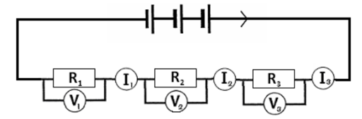
In a series circuit there is a single loop, the current has only one path to take.
In a series circuit, the potential difference is shared between the components.
In a parallel circuit the current has a choice of paths.
In a parallel circuit, the potential difference is the same across each branch and equal to the power supply potential difference.
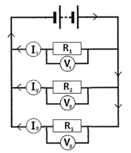
| For components in series: | For components in parallel: |
| · there is the same current through each component I1 = I2 | · the potential difference across each component is the same V1 = V2 |
| · the total potential difference of the power supply is shared between the components VTotal = V1 + V2 | · the total current through the whole circuit is the sum of the currents through the separate components ITotal = I1 + I2 |
| the total resistance of two components in series is the sum of the resistance of each component Rtotal = R1 + R2 | the total resistance of two resistors in parallel is less than the resistance of the smallest individual resistor. |
Power in circuits
Remember the equation linking power, energy transferred and time which we have met before:
Energy transferred = Power x time
E = P x t
P = Power (W)
E = Energy transferred (J)
t = time (s)
We can also link the power, potential difference and current in an equation:
Power = Potential difference x Current
P = V x I
P = Power (W)
V = Potential difference (V)
I = Current (A)
We can also link the power, resistance and current in an equation:
Power = Current 2 x Resistance
P = I 2 x R
P = Power (W)
R = Resistance (Ω)
I = Current (A)
We can also find energy transferred from the potential difference and the charge:
Energy transferred = Charge x Potential difference
E = Q x V
E = Energy transferred (joule, J)
Q = Charge (coulomb, C)
V = Potential difference (volts, V)
GCSE PHYSICS EQUATIONS FLASHCARDS
Everyday electrical appliances are designed to bring about energy transfers.
Work is done when charge flows in a circuit. The work done is the same as the energy transferred.
Mains Electricity
Mains electricity is an AC supply. In the United Kingdom the domestic electricity supply has a frequency of 50 Hz and is about 230 V.
3-pin plug
A plug connects a device to the mains electricity supply.
The insulation covering each wire is colour coded for easy identification:
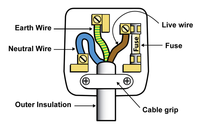
Live wire – brown
Neutral wire – blue
Earth wire – green and yellow
The live wire carries the alternating potential difference from the supply.
The neutral wire completes the circuit. The neutral wire is at, or close to, earth potential (0 V).
The potential difference between the live wire and earth (0 V) is about 230 V.
The earth wire is a safety wire to stop the appliance becoming live. The earth wire is at 0 V, it only carries a current if there is a fault.
The cable between the device and the three-pin plug contains three copper wires that are coated with plastic.
- copper wires are good conductors;
- plastic is a good insulator.
Each part of the plug has a function.
| Features of a plug | Function |
| Outer insulation | All three wires in the cable are bundled together and there is extra plastic insulation wrapped round them all for safety. |
| Cable grip | This holds the cable tightly in place so that wires do not become loose. |
| Live wire | Copper wire coated with brown plastic along which the current enters the device. |
| Fuse | A glass or ceramic canister containing a thin wire that melts if the current gets too high. |
| Neutral wire | Copper wire coated with blue plastic that also connects to the cable in the wall and completes the circuit. |
| Earth wire | Copper wire coated in striped plastic that provides a path for current to flow from the case of the device to the ground if there is a fault. |
The National Grid
The National Grid is a system of cables and transformers linking power stations to consumers.
Electrical power is transferred from power stations to consumers using the National Grid.
Step-up transformers are used to increase the potential difference from the power station to the transmission cables, then step-down transformers are used to decrease, to a much lower value, the potential difference for domestic use.
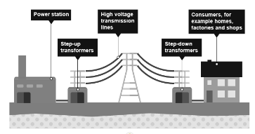
Transformers
There are two types of transformers:
- step up transformers (Increase voltage, decrease current)
- step down transformers (Decrease voltage, increase current)
You can have the same amount of power with a high voltage and low current or a high current and a low voltage. (P = IV)
Transformers are important because if an overhead transmission cable is carrying a large electric current, it heats up and energy is wasted by heating. If instead, the electricity is transmitted at a really high voltage, the current we need to transfer the same amount of energy can be much less and so less energy is wasted as heat.
Electric fields
A charged object creates an electric field around itself.
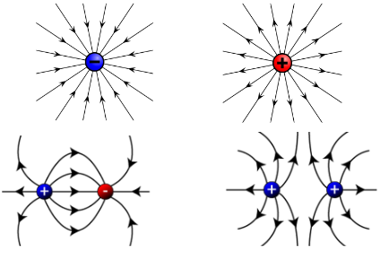
The electric field is strongest close to the charged object. The further away from the charged object, the weaker the field.
A second charged object placed in the field experiences a force. The force gets stronger as the distance between the objects decreases.
Charging by friction
When certain insulating materials are rubbed against each other they become electrically charged.
Negatively charged electrons are rubbed off one material and on to the other. The material that gains electrons becomes negatively charged. The material that loses electrons is left with an equal positive charge.
Electrostatic forces
When two electrically charged objects are brought close together they exert a force on each other. Two objects that carry the same type of charge repel. Two objects that carry different types of charge attract. Attraction and repulsion between two charged objects are examples of non-contact force (they don’t have to be touching for there to be a force).
Required practical: resistance Wire
Use this circuit diagram to set up and connect the circuit.
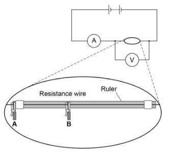
Connect a lead from the negative side of the ammeter to the crocodile clip at the zero end of the ruler. Connect a lead from the other crocodile clip to the negative side of the battery. Use this lead as a switch to disconnect the battery between readings.
Decide the interval distance (eg 10cm) you will investigate and connect the first distance to be tested between crocodile clips A and B.
Measure the readings on the voltmeter and ammeter at this distance.
Record your results.
Move crocodile clip B and record the readings for the different lengths of wire e.g. 20cm, 30cm etc.
Calculate the resistance for each length of wire using the equation:
resistance in Ω = potential difference in V / current in A
Plot a graph of resistance against length of wire.
You should be able to draw a straight line of best fit although it may not go through the origin.
Required practical: Resistors in series and parallel
- Resistors in series
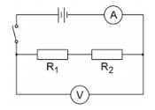
Use the circuit diagram to set up and connect the circuit for two resistors in series R1=R2
Switch on and record the readings of the ammeter and the voltmeter.
Calculate the total resistance of the series circuit (R=V/I).
2. Resistors in parallel
Set up the circuit for two resistors in parallel. Use the circuit diagram below. R1=R2
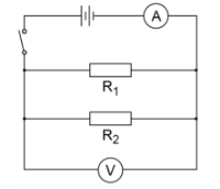
Switch on and record the readings of the ammeter and the voltmeter.
Calculate the total resistance of the parallel circuit (R=V/I).
You should find that….
when wired in series, the total resistance of two resistors is found by adding the resistance of each resistor.
when wired in parallel, the total resistance of two resistors is smaller than the resistance of the smallest resistor.