Electric Circuits simulation (Phet)
Activity: discover how series and parallel circuits work
The aim of this activity is to use the Electric Circuits simulation above (by Phet) to investigate the properties of circuits and to discover some circuit ‘rules’ that always apply to circuits. You are going to take measurements of current and potential difference in series and parallel circuits.
Click on ‘Lab’ to get started.
Series circuits:
A series circuit is one in which all the components come one after the other in a single loop. We say that they are ‘in series’ with each other.
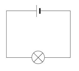
Voltage in a series circuit
1. Make the circuit shown in figure 1.
2. Use the voltmeter to measure the potential difference (voltage) across the battery. Write this down.
3. Use the voltmeter to measure the potential difference (voltage) across the bulb. Write this down.
4. Add additional cells to the circuit and measure the total potential difference across all the cells. Write a sentence describing how to find the total voltage across a number of cells in series.
Current in a series circuit
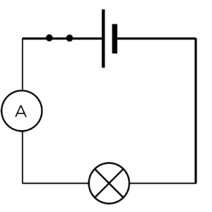
5. Make the circuit shown in figure 2.
6. Try moving the Ammeter to other points within the circuit. What do you notice? Write a sentence describing your findings.
7. Return the Ammeter to the original position and then start increasing the number of cells within the circuit. Write a sentence describing how the current changes.
How varying voltage affects the current
8. Go back to just using a single cell. Right click on the bulb and change the resistance to 10 ohms. Now right click on the battery and change the voltage to the amounts shown in the table below. Record the Ammeter reading for each voltage reading.

9. Describe how the current changes as the PD is increased.
How resistance affects current
10. Now right click on the cell and set the voltage to 25 volts. Keeping the voltage constant, alter the resistance of the bulb and fill in the table below.

11. Describe the relationship between the resistance and the current.
12. Set up the circuit as shown in figure 3. Use an Ammeter to check that your answer to question 6 is still correct.
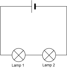
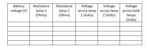
13. Change the resistances of the two bulbs and measure the potential difference across them. Also measure the battery voltage (Keep this constant throughout the experiment) and fill in the table below.
Parallel circuits:
A parallel circuit is one in which all the components each have their own loop to the circuit. The components are said to be in parallel with each other.
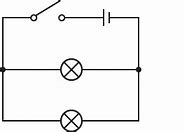
14. Set up the circuit as shown in Figure 4. Close the switch.
15. Take measurements of the current at all points within the circuit. Do you notice a pattern in how the current behaves at the junctions? Write this pattern down.
16. Take measurements of the voltage around the circuit. Do you notice a pattern in the voltage across each component when compared to the battery voltage? Write it down.
This electric circuits simulation is written and shared by Phet (University of Colorado).


